Engineering Fits and Tolerances
- tags Milling Turning Machining Measuring Instruments
- Resources
- NPTEL Design and Manufacturing
- IITB limits and Fits
- Fundamental deviation of shafts Indian System
- Sunil Mohod MetrologyYoutube
- Typical tolerances for manufacturing processes
- ISO code system of linear dimensions
- Engineering Fits wiki
- Machining tolerances
- Geometric Dimensioning and Tolerancing
- Engineering Tolerances Fractory
- Geometric Dimension and Tolerancing Fractory
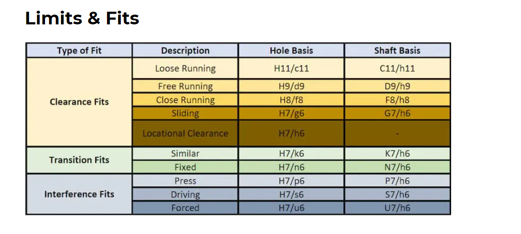
- Limits and Fits
- Notes
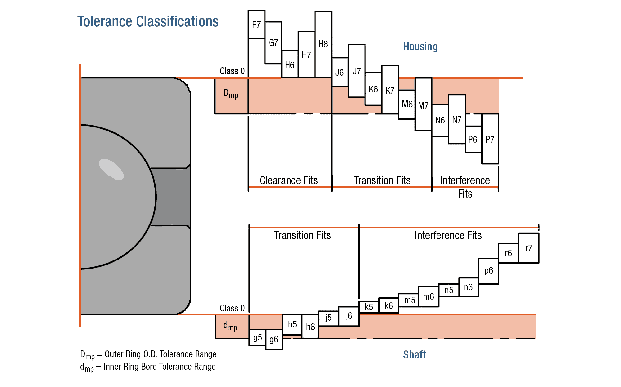
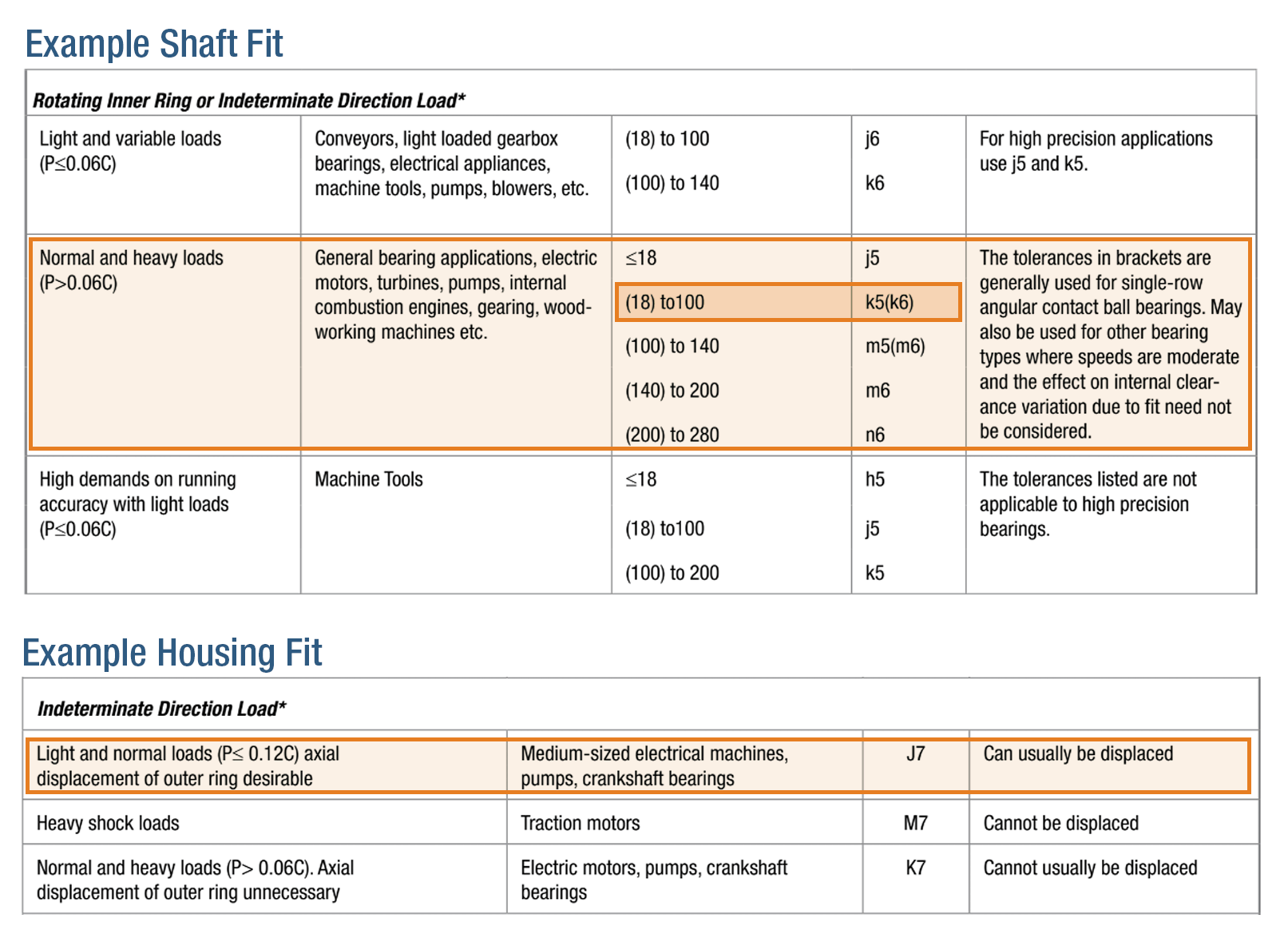
- Bearing and Shaft fits
- Genichi Taguchi and others have suggested that traditional two-sided tolerancing is analogous to “goalposts” in a football game: It implies that all data within those tolerances are equally acceptable.
- Dimensional tolerances are related to but different from fits, which is a designed-in clearance or interference between two parts. Tolerances are assigned to parts for manufacturing purposes they are the boundaries for an acceptable build, since no machine can hold the part to nominal dimension.
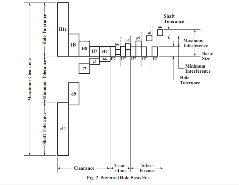
- **Basic size **is the nominal dimension, which is same for hole and shaft. **Upper deviation **is the maximum possible component size and the basic size. **Lower deviation **is the minimum possible component size and the basic size. **Fundamental deviation **is the minimum difference in size between a component and the basic size.
- If a shaft with a nominal diameter of 10 mm is to have a sliding fit within a hole, the shaft might be specified with a tolerance range from 9.964 to 10 mm (i.e., a zero fundamental deviation, but a lower deviation of 0.036 mm) and the hole might be specified with a tolerance range from 10.04 mm to 10.076 mm (0.04 mm fundamental deviation and 0.076 mm upper deviation).
This would provide a clearance fit of somewhere between 0.04 mm (largest shaft paired with the smallest hole, called the Maximum Material Condition - MMC) and 0.112 mm (smallest shaft paired with the largest hole, Least Material Condition - LMC). I
- International Tolerance Grades
- Standard tolerances are divided into two categories, Holes and shafts. They are denoted by the letter ‘H’ (capital for Holes and small for shafts) eg- H7 tapped holes/nut and h7 shaft or bolt. H7/h6 is a common tolerance that gives a tight fit.
- H7 means in ISO fit 10+0.015−0, meaning up to 0.015 mm larger, and 0 mm smaller). h6 would mean 10+0−0.009, which means as small as 0.009 mm and 0 mm larger.
- Machining Tolerances
- Dimensions
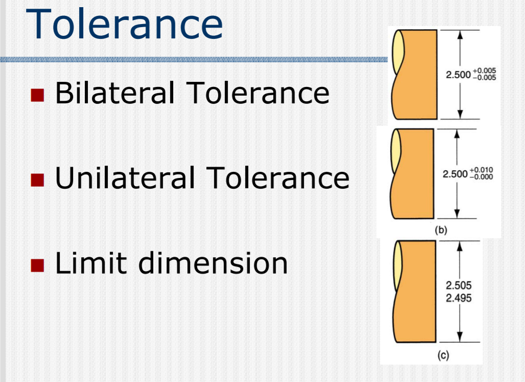
- It is the total amount a dimension is allowed to vary from specified dimension.
- It can be expressed as either a upper/lower limit, allowable above/below a certain value or the variance by itself.
- The difference between the upper and lower limit is the tolerance band and they can be specified by up to 4 significant digits.
-  -
- 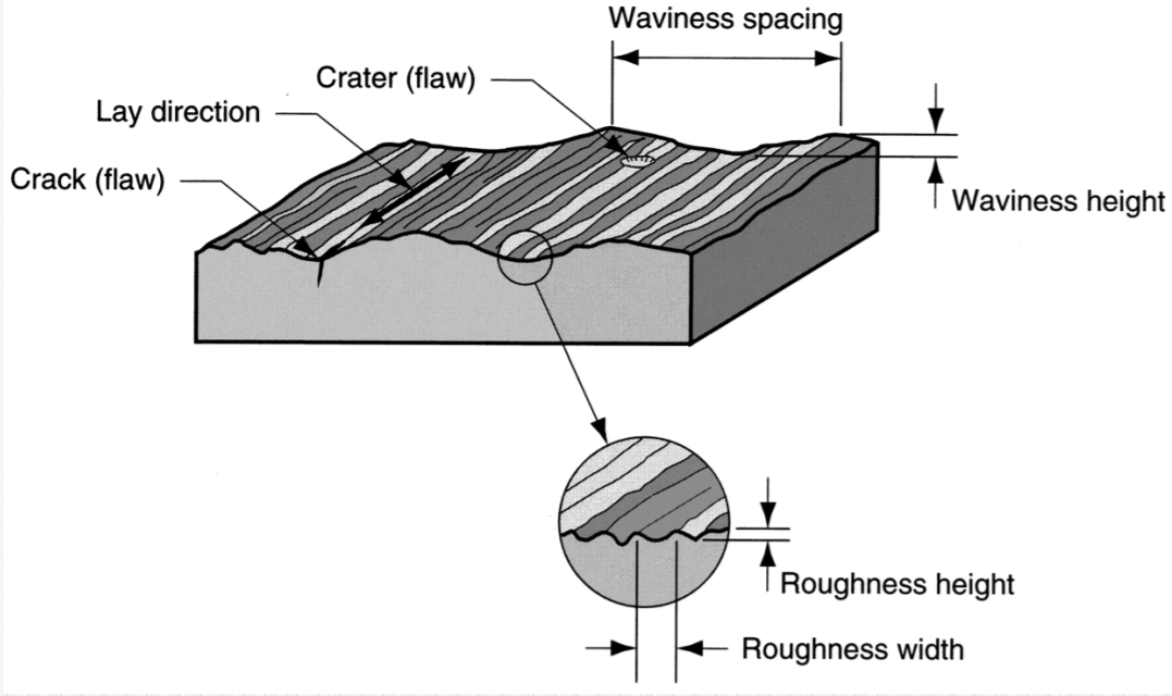 -
- 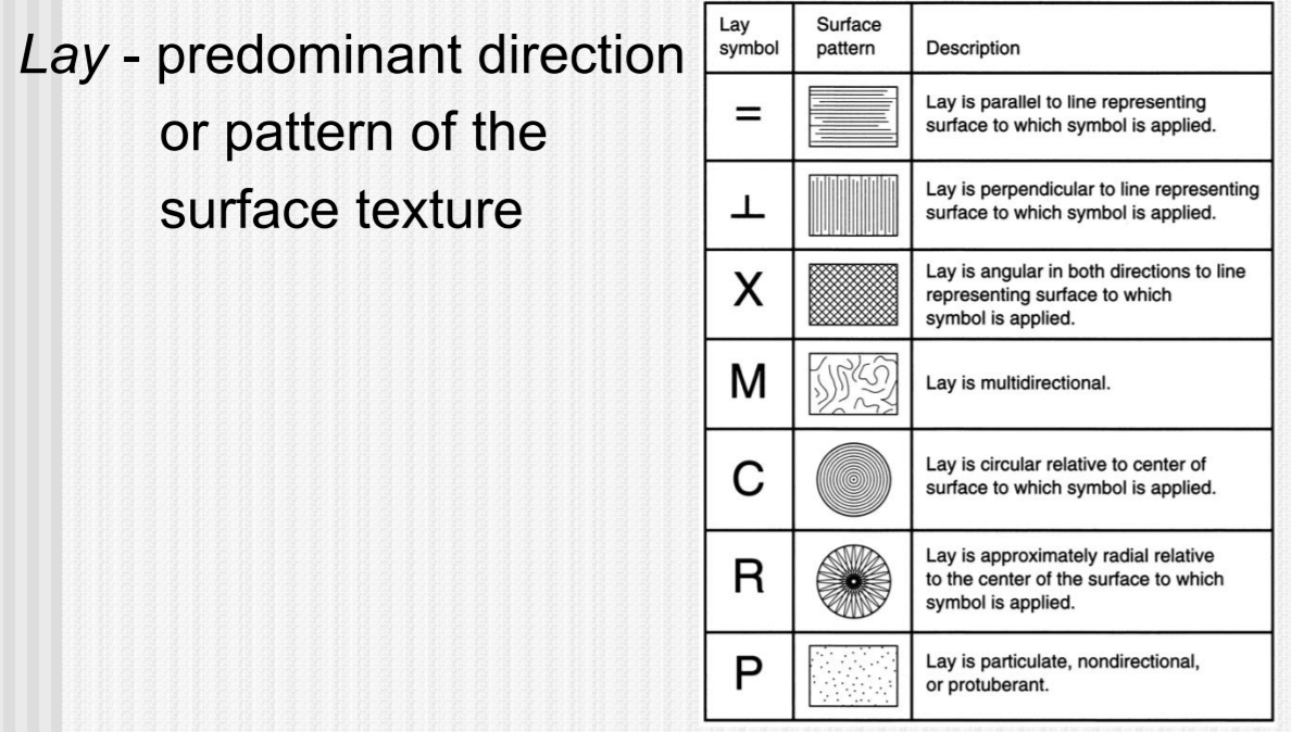 -
- 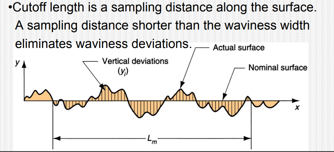 -
-  - Shaft and Hole
-
  -
- 